 |
| March 27, 2018 | Volume 14 Issue 12 |
Designfax weekly eMagazine

Archives
Partners
Manufacturing Center
Product Spotlight
Modern Applications News
Metalworking Ideas For
Today's Job Shops
Tooling and Production
Strategies for large
metalworking plants
How to prevent step losses with stepper motors
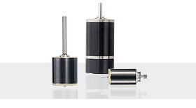
By MICROMO
The use of stepper motors is an excellent choice. However, a key concern is step losses. Step losses can be prevented or corrected in most instances.
Stepper motors operate open loop. When a stepping motor does not operate correctly in a specific situation, the common conclusion is that either the motor or the drive electronics are faulty. The motor selection and the choice of the driver are critical. However, other factors contribute to step losses.
The following points are important to examine for the analysis of step losses or non-operation in a methodical fashion across a variety of applications:
A. Stepper Motor Selection
B. Motion profile
B1. Start-Stop operation
B2. Trapezoidal profile
C. External commutation errors
D. External events
D1. Back driving
D2. Increase of the payload over time
A. Stepper Motor Selection
The first task is to select the right stepper motor for the application. For the best selection, these basic theoretical rules have to be respected:
- Select the motor based on the highest torque/speed point required by the application (selection based on the worst case).
- Use a 30% safety factor from the published torque vs. speed curve (pull-out curve).
- Ensure that the application cannot be stalled by external events.
It is important to remember that a stepper motor does not operate like a DC motor. There is no working point parameterization, and the phase current does not increase to overcome variations of load. As long as the speed vs. torque requirement of the application is within the specs of the motor, no problem will be encountered. If this requirement is out of the specs, the motor stalls (OK or NOT OK functionality). In any case, the current in the phases is not changing and adapting by itself to the situation.
The next step is to qualify the motor with practical tests and verify if step losses occur during operation. Note that by construction, a stepper motor cannot lose only one step. If speed is low, it will lose a multiple of 4 steps (8, 12, 16 ... steps) and if the speed is high, it will stop rotating. In cases where less than 4 steps are lost, the cause is in the commutation.
Since the motor is normally not equipped with a feedback device and since the motor current is not providing any assistance, this is not necessarily an easy task to find the root cause of the failure.
The next sections give some possible root causes in case the qualifications test fails.
B. Operation mode
Depending on the type of motion profile, the analysis is different.
B1. Start-Stop operation
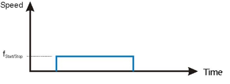
Fig 1. Start-Stop Frequency
In this operation mode, the motor is hooked up to the load and a fixed frequency applied to the driver. The motor has to accelerate the load (inertia and friction) within the first step to the commanded frequency.
Failure modes:
1. Motor does not start
Reasons:
- Load too high => wrong motor, select a bigger motor.
- Frequency too high => reduce.
- If the motor oscillates from left to right, one phase may be broken or not connected => repair.
- Phase current is not appropriate => increase phase current , at least during the first steps.
B2. Acceleration and ramp profile (trapezoidal)
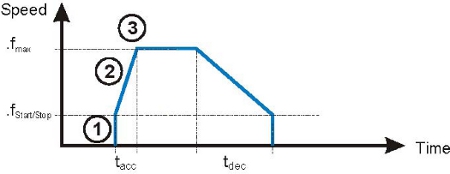
Fig 2. Trapezoidal speed profile
In this case, the motor is allowed to accelerate to the maximum frequency with an acceleration rate preset in the driver.
Failure modes:
1. Motor does not start with set fStart/Stop The situation is the same than in B1 "start/stop operation."
2. Motor does not finish the acceleration ramp.
Reasons:
Motor trapped in resonance frequency
- increase the acceleration to go through the resonance frequency quickly
- select start-stop frequency above resonance point
- use half-stepping or micro-stepping
- add a mechanical damper which can take the form of an inertial disk on the rear shaft.
- increase voltage or current (it is allowed to set a higher value for a short period)
- test lower impedance motor
- use current mode driver (if voltage driver is currently used)
- reduce top speed
- set a smoother and longer acceleration ramp
- try with another driver
3. Motor finishes acceleration but stalls when constant speed is reached.
Possible reasons:
- The motor is operating at the limit of its ability and stalls because it develops too much torque after acceleration. This causes vibrations that the motor may not be able to damp.
Possible solutions:
- Reduce jerk (i.e., select a smaller acceleration rate or use two different acceleration levels, high at start, lower towards top speed.)
- Increase torque and system stiffness when the peak speed has been reached by boosting the current for 3-5 steps. This reduces the vibrations caused by the abrupt acceleration change from Value X to Zero (jerk).
- Add a mechanical damper which can take the form of an inertial disk on the rear shaft. Note that this will add inertia and may not solve the problem in each case if the top speed is at the limit of the characteristics of the motor.
C. External Commutation Errors
As explained earlier, a stepper motor will lose, by construction, a multiple of 4 steps (8, 12, 16 ... steps). If the speed is high, stop rotating (the loss of step lead to a loss of synchronism). If step miscount is not a multiple of 4 steps, the motor is not faulty and the investigation should be focused on the commutation sequence delivered by the electronics.
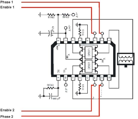
Fig 3. Typical Driver
The shown driver represents a type which can be commanded without any additional control element directly with a 4 bit word. The commutation happens as follows (one phase ON operation mode):
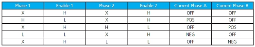
Table 1: One Phase ON Commutation -- typical driver
This sequence is normally not the reason for any failure or step losses during normal operation when current is applied all the time to the phases.
This changes when power is switched off.
Power off of the controller which provides the 4 bits of the example (4 bits for Phase1, Phase2, Enable1, Enable2) will lose the counter status which is required to assure an uninterrupted stepping sequence following the above table.
At power up it is therefore not assured that the counter will find the position it had prior to power-off. If there is a difference between the counter position and the real rotor position, the motor will execute uncontrolled steps. The maximum error may be 2 steps in CCW or CW direction.
Solution
- Before power-off, memorize the 4 bit word (more for more sophisticated drives) and reload it from memory for the counter initialization. Power-on with this position again before continuing the commutation.
D. External events
D1. Back driving
In some cases, the mechanism/load driven by the motor during the movement may wind up and return this energy back to the motor when the currents are switched off. This mechanism may be a reduction gearhead.
As the mechanism returns this energy back, the motor shaft may be rotated backwards. If this back driving is larger than one step angle, the motor will, when the current is switched on for the next movement, not develop sufficient torque to complete the first step. It may not start or start only after 4 full-steps.
This type of failure results also in the loss of at least one commutation cycle of 4 steps for an external commutation error. This failure type may only occur in applications where the motor currents are considerably reduced or switched off after the movement.
Possible solution
- Program the commutation in such way that every time the motor currents are switched off, the same motor current and polarity is applied as applied for the last step before phase current(s) were turned off. Learn more on this possibility in the previous paragraph.
- Instead of powering off, maintain a reduced stand-by current each time the motor is at stand-still.
D2. Increase of the payload over time
In some cases, the motor runs normally for a long period of time but loses steps after some time. In that case, it is likely that the load seen by the motor has changed. It can come from the wear of the motor bearings or from an external event.
Solutions
- Verify the presence of an external event: Has the mechanism driven by the motor changed?
- Verify the bearing wear: Use ball bearings instead of sintered sleeve bearing for extended motor life time.
- Verify if the ambient temperature has changed: Its influence on the bearing lubricant viscosity is not insignificant with the smallest motors. Use lubricants suitable for the operating range. PRECIstep® motors can be obtained with a wide range of lubricants.
Source: MICROMO
Published March 2018
Rate this article
View our terms of use and privacy policy